Pnp Transistor Circuit

Pnp transistor circuit
PNP transistors are used to source current, i.e. current flows out of the collector. PNP transistors are used as switches. These are used in the amplifying circuits. PNP transistors are used when we need to turnoff something by push a button.
What is the circuit diagram of PNP transistor?
| NPN Transistors | PNP Transistors |
|---|---|
| It switches ON when electrons enter the base. | It switches ON when holes enter into the base. |
| The direction of Current is from Collector to Emitter | The direction of Current is from Emitter to Collector |
How does PNP and NPN transistor works?
PNP switches On by a low signal whereas NPN switches ON by a high signal. As we are aware that in PNP transistor, the P represents the polarity of the emitter terminal and N represents the polarity of the base terminal.
Can I use PNP instead of NPN?
Generally, the PNP transistor can replace NPN transistors in most electronic circuits, the only difference is the polarities of the voltages, and the directions of the current flow. PNP transistors can also be used as switching devices and an example of a PNP transistor switch is shown below.
How a PNP transistor works as a switch?
The concept of PNP transistor as a switch is that, the Current stops flow from collector to emitter only when a minimum voltage of 0.7V is supplied to the base terminal. When there is no voltage on Base terminal it works as a close switch between collector and emitter.
Why do we use NPN and PNP transistor?
NPN transistors are used as a sink to the current i.e., current flows to the Collector. It means the current points inwards. PNP transistors are used as a source to the current i.e., current flows out of the Collector.
What is the working principle of transistor?
Well, the very basic working principle of a transistor is based on controlling the flow of current through one channel by varying intensity of a very smaller current that is flowing through a second channel. Also Read: Transistor as a Switch. Transistor as Amplifier.
What is unit of transistor?
The standard units of a transistor for electrical measurement are Ampere (A), Volt (V), and Ohm (Ω), respectively.
What is an PNP?
The PNP transistor is a bipolar junction transistor; In a PNP transistor, the first letter P indicates the polarity of the voltage required for the emitter; the second letter N indicates the polarity of the base. The working of PNP transistor is the exact opposite to the NPN transistor.
Where is NPN transistor used?
NPN transistors are used in applications where a current sink is required. Some classic amplifier circuits, such as 'push-pull' amplifier circuits, make use of this component. In temperature sensors, for example. Applications with extremely high frequency.
What is a PNP junction?
PNP transistor Junctions. A PNP transistor has three terminals - Base (B), Emitter (E), and Collector (C). The emitter and collector are both p-type semiconductors. Base is N-type. In a PNP transistor, there are two types of junctions, the emitter-base junction, and the collector-base junction.
How can you tell PNP from NPN?
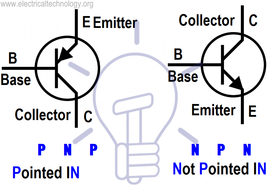
The schematic symbols for NPN and PNP transistors are extremely similar. The sole distinction is the orientation of the arrow on the emitter. It points outward in an NPN (on the left) and inward in a PNP (on the right).
Can PNP used as amplifier?
The PNP transistor can act as a switch and an amplifier.
Are Mosfet NPN or PNP?
An P-Channel mosfet needs a negative Gate - Source voltage to conduct. An NPN transistor needs a positive Base - Emitter current to conduct. An PNP transistor needs a negative Base - Emitter current to conduct. Notice how emitter/collector and source/drain are swapped in the symbols.
Is PNP normally open?
PNP - (PNP transistor) NO – normally opened, that means there is no voltage on the output while the sensor is not actuated (see picture, PNP sensor output connector is no. 4).
Why transistor is used in circuit?
A transistor can act as a switch or gate for electronic signals, opening and closing an electronic gate many times per second. It ensures the circuit is on if the current is flowing and switched off if it isn't. Transistors are used in complex switching circuits that comprise all modern telecommunications systems.
Why NPN is better than PNP transistor?
The mobility of electrons is better than the mobility of holes. Mobility of electrons is more than hole, so as a result n-p-n transistors are faster than p-n-p that's why they are preferred.
Why transistor is used as a switch?
The transistor can be used as a switch if biased in the saturation and cut-off regions. This allows current to flow (or not) in other parts of a circuit. Because a transistor's collector current is proportionally limited by its base current, it can be used as a sort of current-controlled switch.
What is a PNP output?
A PNP output is commonly called a “sourcing” output. When it senses an object it will connect the output to the positive supply. If you're unsure of which output type you need, a number of manufactures produce sensors with configurable outputs. In this case the sensor can be configured to operate as an NPN or PNP type.
Which transistor is most commonly used?
The MOSFET is by far the most widely used transistor for both digital circuits as well as analog circuits, accounting for 99.9% of all transistors in the world. The bipolar junction transistor (BJT) was previously the most commonly used transistor during the 1950s to 1960s.
15 Pnp transistor circuit Images
S8050 Transistor Circuit Diagram Rangkaian elektronik Teknologi

PNP Transistor Tutorial The Bipolar PNP Transistor Electronics

Transistors as two diodes Engineering Science Electronic Engineering

multivibrator based on npn and pnp transistor Circuit diagram

PNP TRANSISTOR AS A SWITCH Transistors Turn ons Led lights

PNP Transistor As A Switch Transistors Basic electronic circuits

Darlington Transistor Pair Dc Circuit Circuit Diagram Electronics

PNP and NPN Darlington Pair Transistor Amplifier Circuits Transistors

PNP Transistor Switches Circuit Electronics Components Ham Radio

LM339 comparator driving relay with external PNP transistor in 2021
Pin on electronics

Pin on transistor

Working of Transistor as a Switch NPN and PNP Transistors

Single Transistor Radio Receiver Circuit Transistor radio First
Post a Comment for "Pnp Transistor Circuit"